Automated Test Equipment
Introduction
Sound Bite: The ATE74IC can automatically test a variety of 74-series integrated circuits with the press of a button, preventing users from wasting time with faulty circuits.
Summary: The ATE74IC is a testing device that tests the validity of each gate within each IC chip. This project tested specifically 6 IC chips: NAND, NOT, OR, AND, D Flip Flop, and NOR. These are common chips used to design complex ASIC designs and processors. Ensuring these chips work is crucial in developing digital electronics as they are vital to developing everyday systems that people use.
Rationale and Sources:
Automated test equipment is used extensively in the semiconductor industry to quickly test chips for manufacturing flaws; as integrated circuits and systems-on-chip grow increasingly complex, testing each internal connection becomes difficult, so equipment to automatically run tests becomes necessary. However, aspects of semiconductor testing, including Design for Test, post-silicon validation, and automated test equipment, are rarely mentioned in undergraduate-level courses. Additionally, having equipment to test ICs commonly used in digital electronics courses would be greatly beneficial, as would save time working with faulty chips. We designed the ATE74IC to provide an accessible interface for undergraduates to test simple 74-series ICs.
Background:
A selection of 7400-series integrated circuits were chosen as the units-under-test (UUTs) for this project since the 7400-series is an industry standard commonly used in many digital electronics courses. These logic ICs implement fundamental Boolean functions (AND, OR, NAND, NOT) and sequential elements like (D flip flops) in a 14 pin package. The pinout conventions and well documented specifications make them really suited for this project.
ATE systems verify electronic component functionality through a computer controlling testing scheme without manual intervention. Our implementation focuses on functional testing by applying systematic input patterns to the IC and comparing the measured outputs against expected values derived from truth tables. For combinational logic gates, we use exhaustive truth table verification that tests all possible input combinations. For sequential circuits like D flip-flops, we employ clock cycle based validation that verifies state transitions over multiple clock edges.
The user interface leverages VGA display to provide clear visual feedback. Using Hunter Adam’s VGA library for the RP2040’s dual core architecture allows one core to handle the timing of the VGA signals while the other manages test execution and user interactions. The display shows IC package representations with color coded pins to show pass/fail.
To enhance useability, we incorporated audio feedback using pre-recorded speech samples played through an SPI connected DAC. When the system detects either pass or fail, it plays corresponding audio messages that alert users to the failure type. This auditory confirmation allows users to identify problems immediately without needing to constantly watch the display.
High Level Design
Logical Structure:
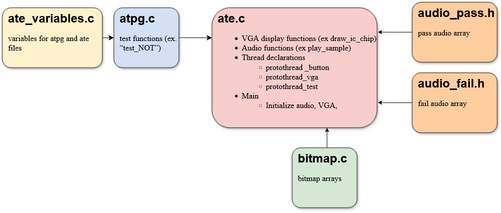
We found it most intuitive to divide the code into multiple files for this project due to the scope and necessity of asynchronous work. We put the “main” function, all code for protothreads, button, VGA, LED, and DAC in a file entitled “ate.c”. However, all test functions were placed in a file titled “atpg.c”, (Automated Test Pattern Generator). Variables needed in ate.c and atpg.c are in a “ate_variables.c”, which is included in atpg.c. Additionally, due to the length of bitmap arrays, they were placed in a separate file entitled “bitmap.c.” Similarly, the arrays encoding the audio samples were placed in separate header files (“audio_pass.h” and “audio_fail.h”).
Additionally, we used semaphores to control when VGA and test protothreads ran; for example, calling the VGA semaphore after the button to toggle between ICs is pressed.
Hardware/Software Tradeoffs:
Since 7400-series ICs have 12 pins (not counting ground and VCC pins), we realized the number of GPIOs we had on a standard RP2040 would be inadequate if we wanted to also use buttons, LEDs, and a DAC. We decided that these were all important elements of the project which we did not wish to sacrifice, so we obtained a port expander (the MCP23s17). The port expander allows us to provide more digital I/O to the RP2040 at the expense of a slower clock rate. Since the test functions are relatively simple, the slower clock cycle was imperceptible to results speed.
Additionally, many design decisions, such as the extensive use of functions and text variables, were the result of prioritizing simplicity and readability by humans over space or time constraints. Since the project was not especially space or time-intensive, we did not worry about those as constraints, and instead aimed to make the code and display intuitive for us to create in our four-week timespan as well as for the target demographic of undergraduate students.
Program/hardware Design
Hardware:
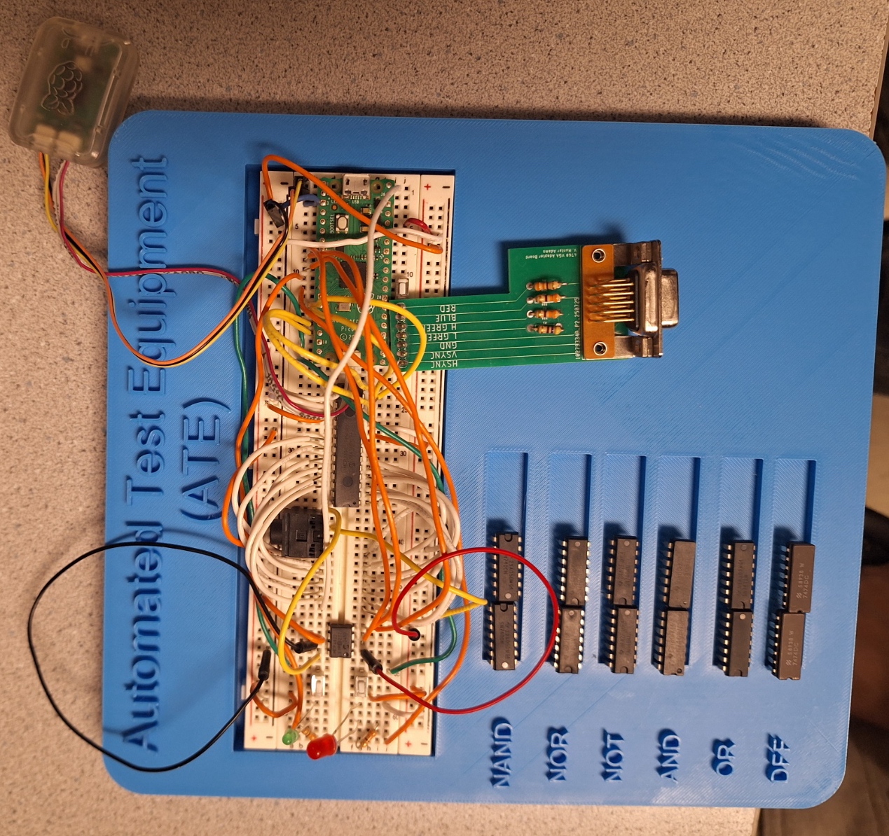
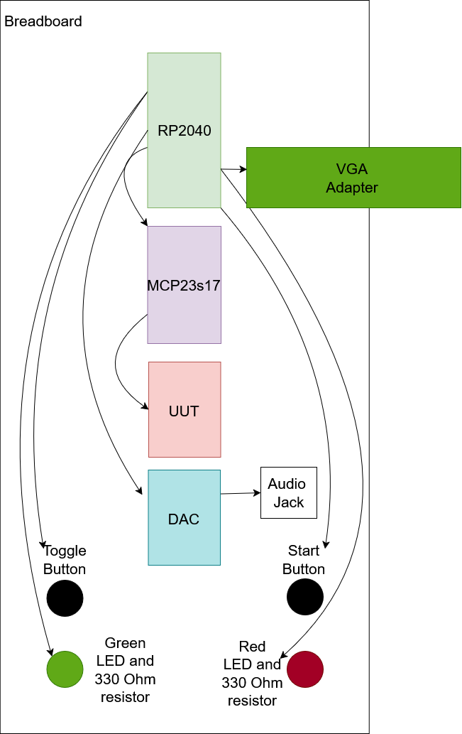
The ATE74IC hardware centers around the RP2040 microcontroller, which handles test operations, manages the user interface, and generates VGA display output. To solve our GPIO pin limitations when interfacing with 14-pin ICs while supporting buttons, LEDs, and display generation, we decided to use an MCP23S17 SPI port expander to provide 16 additional bidirectional I/O pins. This was suggested by Bruce Land and it allowed dynamic configuration of each IC pin as input or output during testing. The user interface features two push buttons (IC selection and test start) and red/green status LEDs for immediate visual feedback. The VGA subsystem uses a resistor based DAC network to generate color signals, displaying the IC under test with color coded pins. Audio feedback is delivered through an SPI DAC and 3.5mm audio jack, playing pre-recorded messages for test results.
- RP2040
- Port expander (MCP23s17)
- LEDs (One red and one green)
- Buttons (two)
- Two 330 Ohm resistors
- VGA
- VGA adapter
- DAC
- Audio Jack
- Wires
- 7400-series ICs (7400, 7402, 7404, 7408, 7432, 7474)
| RP2040 Pin | Connection |
|---|---|
| GND | VGA GND, DAC GND, Port Expander (VSS, AIN0, AIN1, AIN2), IC Pin 7 |
| 3.3 V | DAC VCC, Port Expander (VDD, Reset), Toggle Button, Start Test Button |
| 5 V | IC Pin 14 |
| RP2040 GPIO Port | Connection |
|---|---|
| 2 | DAC timing ISR |
| 5 | DAC Chip select |
| 6 | DAC SCK |
| 7 | DAC MOSI |
| 8 | Green LED |
| 9 | Red LED |
| 10 | Port Expander SCK |
| 11 | Port Expander TX |
| 12 | Port Expander RX |
| 13 | Port Expander CS |
| 14 | Toggle Button |
| 15 | Start Test Button |
| 16 | VGA Hsync |
| 17 | VGA Vsync |
| 18 | 470 ohm resistor -> VGA Green |
| 19 | 330 ohm resistor -> VGA Green |
| 20 | 330 ohm resistor -> VGA Blue |
| 21 | 330 ohm resistor -> VGA Red |
| Port Expander Port | IC Pin |
|---|---|
| A0 | 8 |
| A1 | 9 |
| A2 | 10 |
| A3 | 11 |
| A4 | 12 |
| A5 | 13 |
| B0 | 1 |
| B1 | 2 |
| B2 | 3 |
| B3 | 4 |
| B4 | 5 |
| B5 | 6 |
Software:
As discussed above, we divided software into protothreads and files to divide functionality.
ATPG:
“ATPG” stands for Automatic Test Pattern Generator, and in industry, this is a part of an ATE or on-chip Built-In-Self-Test system which generates test cases to try to achieve full coverage of all connections on the chip. However, for the scope of this project we hard-coded test cases, which was a far simpler way to achieve coverage since the number of possible values is very low for 74-series ICs. The “atpg.c” file includes functions to test each 74-series UUT. While the test cases themselves were relatively simple; we ran into several challenges in this section of the project. The most immediately obvious problem was that the RP2040 has only twenty-five GPIO pins available, and we needed twenty-six to incorporate all of our desired functionality, as discussed in the Hardware-software tradeoffs section. As a result, we had to use a MCP23s17 port expander and an associated library provided by Bruce Land in the ATPG test functions. We set up port expander directions, and reset output LEDs and stored results at the top of each function, then proceeded to cycle through each test case. For each test case, we set the port expander outputs / UUT inputs to selected test values, then stored the UUT outputs in an array, which we checked for accuracy to expected values. These results were then output to the VGA, followed by the start of the next test case. This was our next challenge; transferring results to the display; this was solved by writing to a thoughtfully designed system of structs and arrays in the “ate_variables.c” file. Finally, testing the D-Flip-Flop IC (7474) was slightly challenging since it required multiple cycles of the clock pin to test. To simulate this, we cycled the clock in increments of five microseconds using a sleep function.
Buttons:
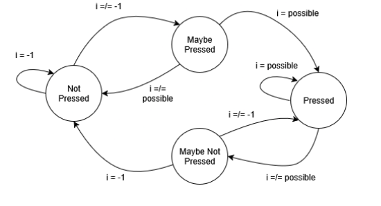
The button control was confined to the thread “protothread_button”, and relied on a debouncing state machine for each button. On the transition from the “Maybe Pressed” to “Pressed” state for the “Gate Select” button, the ic_name variable for the current test is updated to the the next gate, where each gate is represented by an integer between zero and six, and the integer is incremented on the state transition. Similarly, the “Start Test” button calls the test_semaphore to run the test protothread on the transition from MAYBE_NOT_PRESSED to NOT_PRESSED. Choosing to place the test functionality in a separate protothread called by a semaphore allows control over when tests are run. This way, the operator can ensure the setup is correct before running, view test results in real time, keep test results up as long as desired, and rerun when ready.
VGA Screen Top-Left IC chip Test Bed & Bitmap:
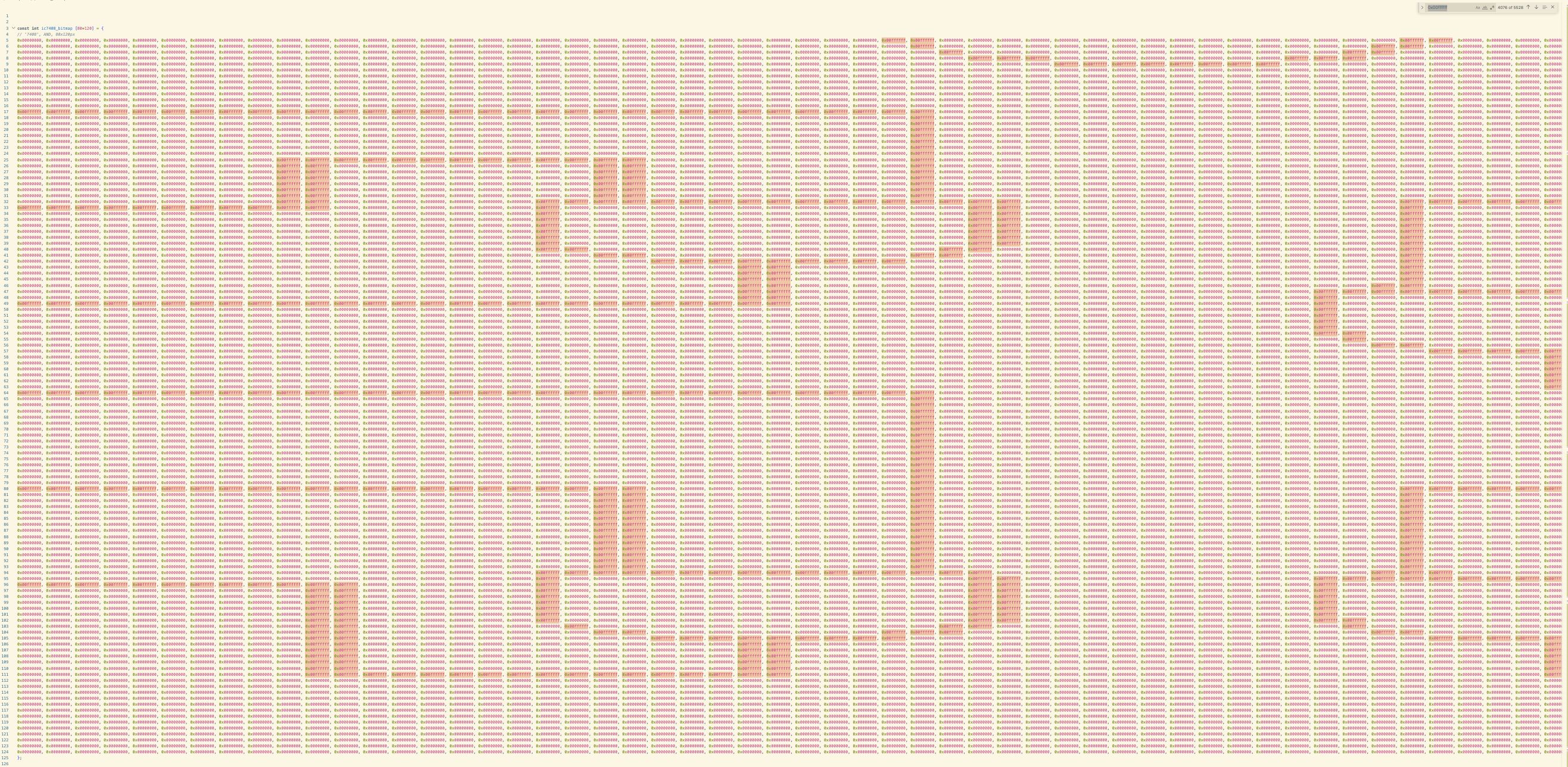
The top left section of the VGA screen displays a visual representation of the IC chip test bed, showing the chip outline with pin numbers and connections that highlight in red when a pin fails a test. Black and white line-art images of 7400-series IC chips (7404 NOT, 7408 AND, 7400 NAND, 7432 OR, 7402 NOR, 7474 DFF) were sourced from Google and converted to bitmap arrays using an online image-to-bitmap converter tool, image2cpp. However, many of the Google images were too blurry, resulting in bitmap representations where the gate symbols were hard to read, pin labels didn't align properly with the test bed connections, and some gate triangles had missing lines. To fix these issues, we manually edited the bitmap arrays in bitmap.c, modifying the 0x00FFFFFF (white) and 0x00000000 (black) hex values pixel by pixel to clean up the gate symbols, straighten lines, and ensure the chip diagrams were legible and properly aligned. The draw_ic_chip() function renders these bitmaps by iterating through each pixel and calling drawPixel(), while draw_pin_connection() draws the pin labels and connection lines, changing the color to red and using fillRect() instead of drawLine() for any pins marked as failed in the current_test struct.
VGA Screen Top-Right Real-Time Test Progress:
The top right section of the VGA screen displays real-time test progress through the draw_error_messages_display function, which shows the current test number (for example, “Test 2 of 4”), the current status message indicating which gate is being tested (for example, “Runnng test 2 on gate 1…”), and a list of gate results that updates as each gate completes testing. The TestProgress struct in ate_variables.c tracks these informations with fields for current_test_num, total_tests, current_gate_num, total_gates, current_status, gate_results[], and a test_in_progress flag. During testing, atpg.c updates these fields and calls update_vga_display() to reflect these changes. If the gate failed a test, the result in displayed in red. The test_in_progress flag turns false, and the final frame shows all gates complete testing, and a list of gate test results.
Audio:
To achieve audio output, we connected a MCP4822 12-bit DAC to the RP2040 via SPI communication. The DAC output connects to an audio jack, which connects to the speaker. We generated two audio clips, “All tests pass; the IC chip works correctly” or “Some tests failed; the IC chip might be faulty” using a text to speech website, TTSMP3. Next, we converted the MP3 file to an uncompressed, WAV file ((uncompressed, sample rate 8000 Hz, 8-bit unsigned, mono channel) using another online converter, FreeConvert. Finally, we converted the WAV file to C array header (code format hex 0x00, data type uint8_t, unsigned) using FileToCArray. We initialized the SPI ports in ate.c, and played the two audio samples by looping through the two arrays, scaling each of the 9-bit sample to 12-bit for our 12-bit DAC, and sending it via SPI. Audio error messages are played after each test completes, based on the test results.
The “atpg.c” file includes functions to test each UUT.
AI Use
We used AI (ChatGPT) to generate some code, but all code was heavily modified from the ChatGPT output. The main use case was getting an example of how to do something in C which we didn’t already know how to do.
Results
Our testing revealed that the ATE worked for all test ICs.
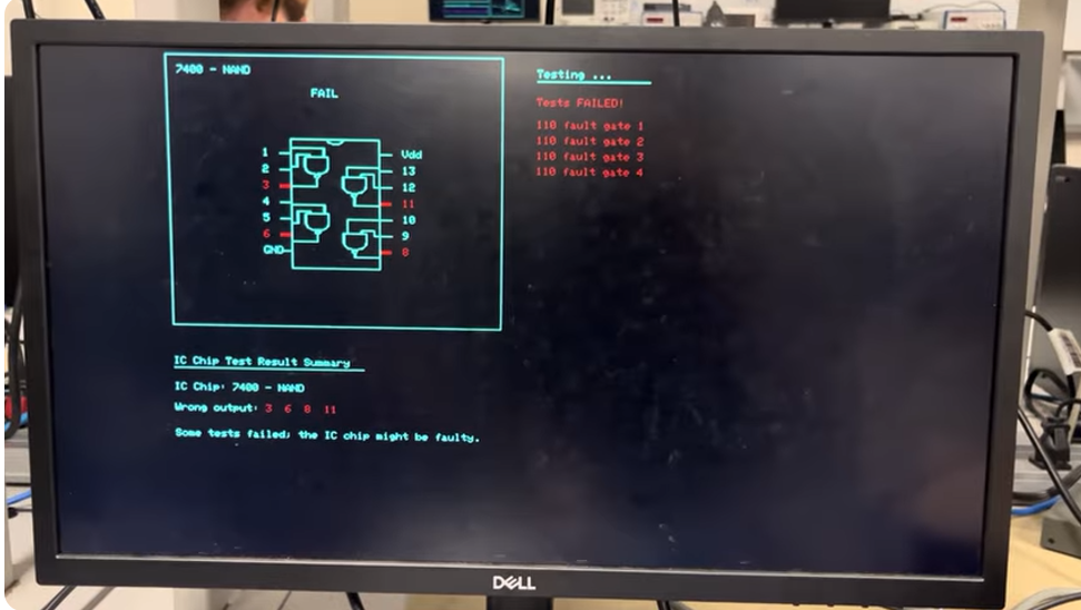
The top left of the VGA screen highlights failed pins in red. The top right of the VGA screen displays test results in real time while the test is running. The green “Overall Pass” LED lights up only when all test cases for all gates pass, while the red “Overall Fail” LED lights up when one or more test cases fail. The bottom section of the VGA screen displays a results summary, indicating which output pin produces an incorrect value. An audio version of the results summary also plays. We added audio output to enhance accessibility for users who may have difficulty seeing the display. In a future version of this project, we plan to expand the audio feedback to provide more detailed messages, rather than only the two current messages: “All tests pass; the IC chip works correctly” or “Some tests failed; the IC chip might be faulty.”
The top right section of the VGA screen shows, in real time, which gate on the IC is currently being tested, as well as which test case is running. A sleep_ms delay was added to the program to slow down the testing process, allowing this portion of the VGA display to update visibly. Without sleep_ms, the test completes in less than one second, causing the top right section of the VGA screen to display only its final frame, the summary of the specific tests that failed.
We tested two units of each 7400-series IC chip. As demonstrated in the demo video above, one of the 7400 NAND chips sourced from DigiKey was defective. As expected, our automatic test equipment correctly identified this damaged chip and reported a failed result.
We also intentionally shortened some of the input or output pins of the ICs to ground, VCC, or to each other to induce failures. In these cases, the top right section of the VGA screen correctly indicated a failure at the output associated with the shorted pin, along with the specific failed test case (for example, “110 fault gate 1”, indicating that when two logic-high inputs were applied to a NAND gate, the expected logic-low output was not observed and a logic-high output was produced instead).
| 7400-series IC Type | Test Results |
|---|---|
| 7400 (NAND) | One chip pass, one chip fail |
| 7402 (NOR) | Both chips pass: Green light works. Displays expected error messages. |
| 7404 (NOT) | Both chips pass: Green light works. Displays expected error messages. |
| 7408 (AND) | Both chips pass: Green light works. Displays expected error messages. |
| 7432 (OR) | Both chips pass: Green light works. Displays expected error messages. |
| 7474 (DFF) | Both chips pass: Green light works. Displays expected error messages. |
Conclusion
Our ATE74IC successfully met its primary objective of automatically testing the 74-series logic ICs with a single debouncing button that switches between the different gates. The system accurately identifies and tests common logic gates (AND, OR, NOT, NAD, NOR, XOR, D Flip Flops) and displays results on a VGA monitor and circuit board LED with clear pass fail indicators. The RP2040 did not have enough GPIO pins so we used a port extender and it worked well. The truth table verification proved to be reliable for combinational logic testing. The user interface provided very clear feedback and is very intuitive for the users to understand. This application is good for educational or hobbyist applications.
Next time, we believe we can have a more expanded IC library since we are only limited to basic gates and flip-flops. We can also include counters, registers, and more complex 74 series devices. Also, having a data logging system that allows exportation of test results via USB serial would be helpful for sharing among teams.
For code, we utilized Hunter Adam’s VGA graphics library for the RP2040, which is publicly available and documented for educational use in ECE 4760 class. The standard pico sdk libraries were used for GPIO control, spi communication, and hardware timers. Additionally, we used the MCP23S17 port expander library (mcp23s17_rp2040.h) provided by Bruce Land for spi-based GPIO expansion functionality. The test generation logic (atpg.c), user interface, the IC tests and state controls were our own original work. The IC chip visual representation displayed on the VGA interface use bitmap images so it would look neater on the VGA. These graphics are our original artwork based on standard IC package appearance and are not from any copyrighted material.
In terms of public domain usage, 74-series IC specifications are based on decades old designs now in the public domain. Logic function definitions are Boolean operations not subject to intellectual property protection. Truth tables and timing requirements were derived from publicly available datasheets from manufacturers (Texas Instruments, NXP, ON Semiconductor). We did not reverse engineer any commercial ATE system. Our test methodology is comparing actual IC outputs against expected truth tables. No proprietary testing algorithm or commercial test equipment designs were replicated.
Patents and trademarks: the 74 series is not trademarked because it is industry standard. Commercial ATE patents exist but are much better than our educational implementation. All components are standard commercial parts with no NDAs. This project presents no patent opportunities as IC testing is well-established technology
Work Distribution
Michelle Yang: Wiring of all components, code for audio output, IC chip display, and test result display.
Diane Pillsbury: Code for Testing each IC chip and connections with port expander.
Xia Yan Zhao: Minimal coding/initial version of IC chip display, CAD and 3D printed blue exterior.