Synthesizing Birdsong
Introduction
The goal was to design a bird song synthesizer that synthesizes one of the most common songs of the northern cardinal on a Raspberry Pi Pico with the RP2040 processor. We use direct digital synthesis to generate a pure sine wave “beep,” then amplitude modulate the beep to produce “swoop” and “chirp,” in an attempt to trick Cornell Ornithology’s Merlin Bird ID App. We control the synthesizer with a keypad, to associate pressing button 1 with “chirp,” button 2 with “swoop,” button 3 with “silence,” and developed record and playback modes (interface by pressing button 4 and 5 respectively) to capture and reproduce the song sequence with precise timing.
Design and Testing Methods
General:
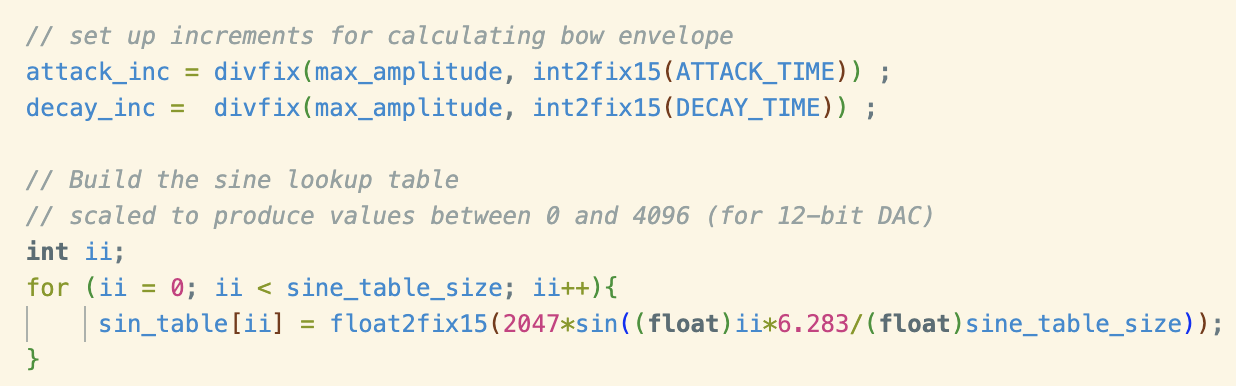
In the main part of the program, we initialized the serial interface, map the GPIO ports to the DAC pins, the GPIO ports to the on-board LED (for signaling entering protothread later on), set up the timing ISR, pre-calculate the bow envelope increments, build the sine lookup table, initialize the keypad, and identified 2 functions, photothread_core_0 (keypad thread) and protothread_playback to scheduler.
The bow envelop calculation is needed to slowly ramp up and down the sinewave, to prevent high frequency “pops” and “clicks” in the generated speaker output sound. The sine lookup table produce values between 0 and 4096 (2^16), the range of data the DAC will receive. The sine lookup table will be index into when performing direct digital synthesis in the timer ISR.
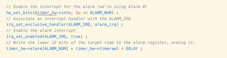
In the main, the timer interrupt is enabled, associated with its interrupt handler function, and armed for the first time by writing the lower 32 bits of the target time (DELAY time passed current time) to the alarm register.
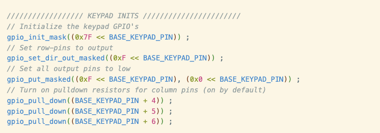
To interface with the keypad, all 7 keypad buttons are inialize with corresponding GPIO pins. The row pins are set to output and are connected in series with external 330 ohms pull down resistors, and column pins are set to input with internal pulldown resistors turn on.
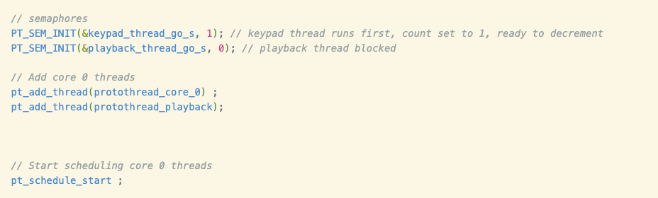
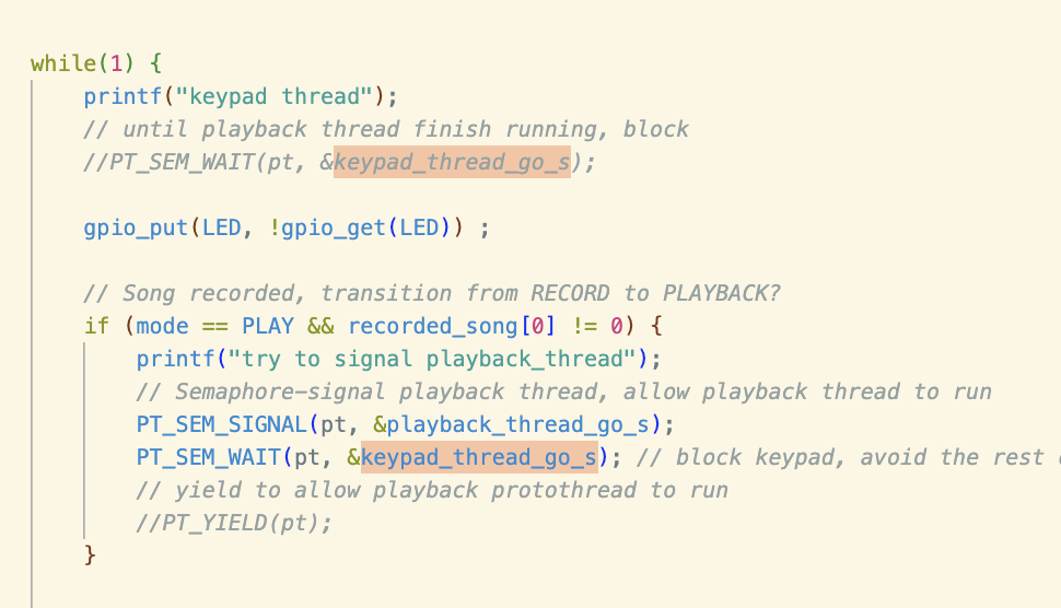
Two core-safe (although only core 0 is utilitized) semaphores are used to ensure the precise alternation between the keypad thread and the playback thread. These semaphores are initializefd before starting either of the two proto-threads (keypad thread and playback thread). Since we want the keypad thread to run automatically when program reboot, we set the keypad_thread_go_s initial count to 1, and the playback_thread_go_s initial count to 0, to block the playback thread while the keypad thread runs. If a song is recorded (the recorded_song length 30 array is not empty) and the playback button is pressed, the keypad thread signals the playback thread (increment playback_thread_go_s semaphore) to playback the recorded song, and after the playback thread finish reproducing all the songs (by sending array’s stored button press to timer ISR) and resets the array, the playback thread signals back to the keypad thread (increment keypad_thread_go_s semaphore) to starting scanning for valid keys again. At the end of main, we start the scheduler to schedule the core 0 threads (keypad thread and playback thread).
Timer ISR:
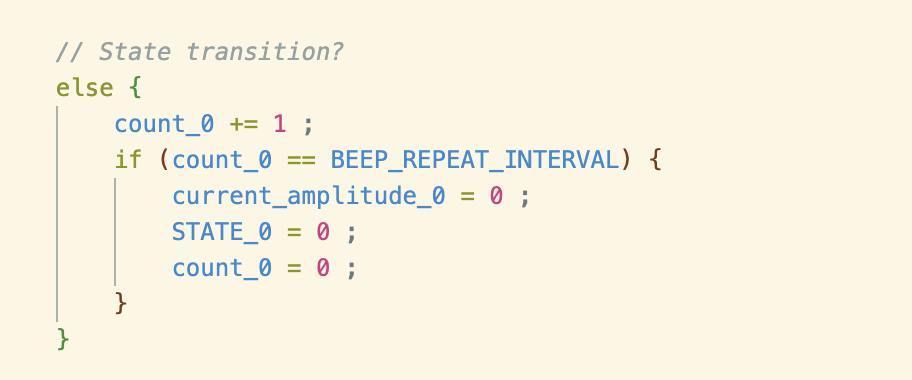
We first combined the audio beep-beep demo code with the keypad demo code to associate a button press on the keypad with the production of a pure sine wave “beep.” The beep-beep demo code fires an interrupt once per second, generating a 400 Hz beep through an SPI DAC. We removed the state transition else statement from the beep-beep ISR to prevent repeated “beep” production. When a button press, a sound is generated (in state 0) , then the state transitions to state 1, and stays in state 1 until another valid button press.
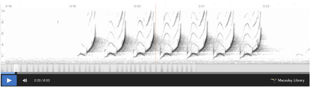
“The song of a northern cardinal can be decomposed into three sound primitives: a low-frequency swoop at the beginning of each call, a chirp after each swoop which moves rapidly from low frequency to high frequency, and silence which separates each swoop/chirp combination” (Synthesizing Birdsong via Direct Digital Synthesis webpage).
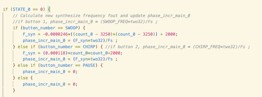
Using if-else statements, we associate button press with the desired sound. If button 1 is pressed, produce a “swoop” sound. If button 2 is pressed, produce a “chirp” sound. If button 3 is pressed, produce a silent “pause” sound.
We set the phase incrementor angle to index into the sine lookup table, to obtain a value to send to the DAC, to produce our desired sound. We observe from the spectrogram that the “swoop” of the song looks like the first half of the sine-wave, the “chirp” of the song looks like the second half of an upward parabola, and the “silence” of the song is a constant frequency of 0. We found the desired frequency function with count_0 as the dependent variable for the “swoop” and “chirp.”
Note that the length of these sound primitives are 130ms, so they all last for:
0.130 sec ⋅ 50000 samples (since DAC gathers audio staples at Fs = 50KHz)/1 sec
= 6500 samples
We can approximate the frequency curve of the “swoop” by a sine wave of the form:
Fdesire = F_syn = ksin(m*count_0 + b)
but the sine math function is too expensive and using it directly will cause us to miss the timing ISR deadline. We could choose to build another sine look up table to utilize the sine wave approximation, but we decided to go with a simpler quadratic approximation. The frequency curve of the “swoop” also looks like an upward pointing parabola, approximated by the form:
Fdesire = F_syn = a(count_0 - h)2 + k (in vertex form for easier calculation of parameters)
And finding unknown parameters a, h, and k by plugging in known points (count_0, F_syn).
We can approximate the frequency curve of the “chirp” by a quadratic equation of the form:
Fdesire = F_syn = k(count_0)2 + b
and finding unknown parameters k, b, and m by plugging in known points (count_0, F_syn).
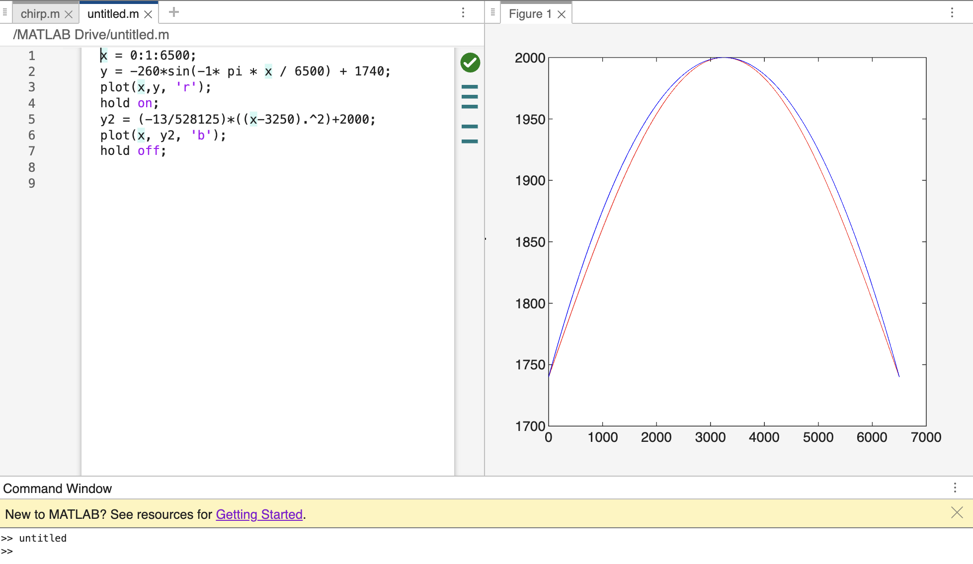
For “swoop,” it is known from the spectrogram that the curve starts from a frequency of 1740 Hz, raise to a maximum/peak of 2000 Hz at 6500/2 count_0 interrupt sample, and then fall back down to 1740 Hz at 6500 count_0 interrupt sample. The unknown parameter a, h, and k are found by plugging in (0, 1740), (6500/2, 2000), and (6500, 1740), to obtain a = -13/528125, k = 2000, and h = 6500/2. Thus, in vertex form, Fdesire = F_syn = (-13/528125)(count_0 - (6500/2))2 = 2000.
For “chirp,” it is known from the spectrogram that the curve starts from a low frequency of 2000 Hz and raises to a high frequency of 7000 Hz after 5200 interrupt samples (count_0 start from time 0 to time 5200). The unknown parameter k and b are found by plugging in (0, 2000) and (5200, 7000), to obtain k = 1.18 * 10-4, b = 2000. Thus, Fdesire = F_syn = (1.18 * 10-4)(count_0)2 + 2000.
We also used matlab to plot the desired frequency formulas to make sure they relatively look like the “swoop” and “chirp” curves of the Northern Cardinal. The “swoop” plot also compares what the curve will look like if approximated by sine wave instead of quadratic.
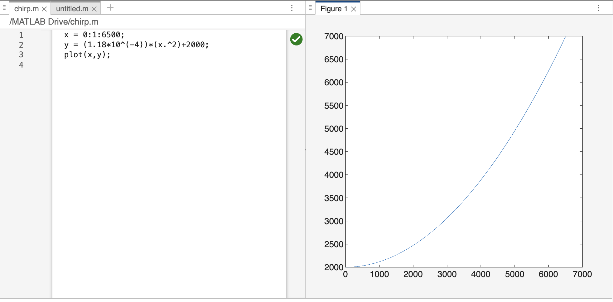
The manipulated desire frequency determines the phase incrementor angle to index into the sine lookup table, to send value through the SPI transmit buffer to DAC to produce desire sound via speaker.

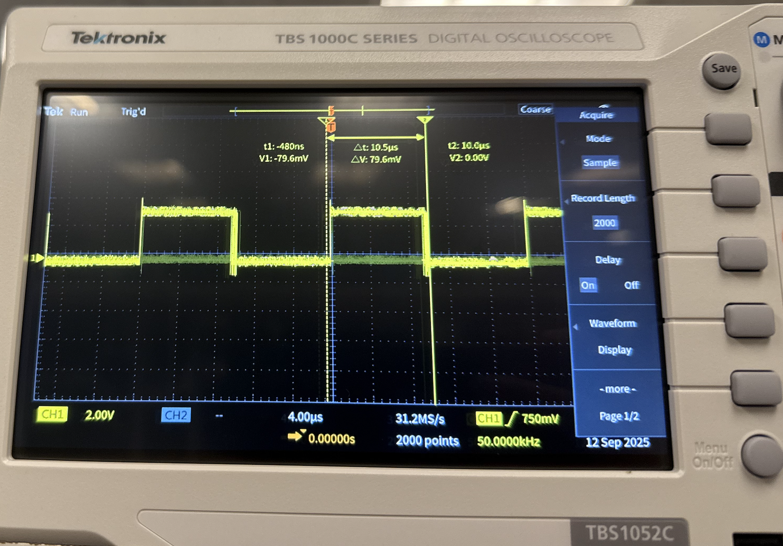
At the beginning of the timer ISR, we set a GPIO high, to signal entering the ISR, and in the end of the ISR, we set the GPIO low to signal leaving the ISR. This allows us to hook up the specified GPIO pin to an oscilloscope, allowing us to measure how long we were in the ISR, verifying that we met the timing requirement.
Keypad Thread:
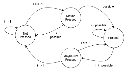
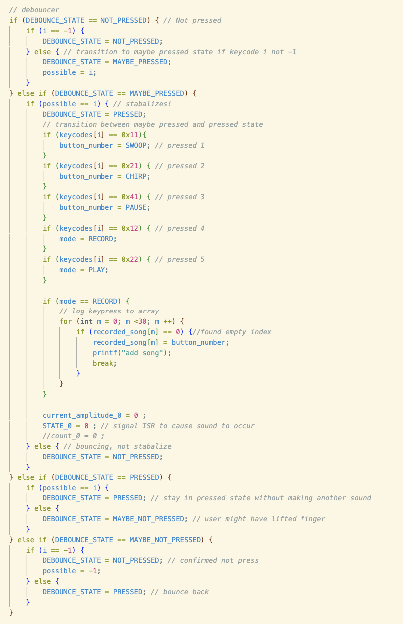
Underneath the keyscan code, we implemented a debouncer for key press using a state machine. No matter how long a key is pressed, one sound is produced (“swoop,” “chirp,” or “pause”).
The debouncer prevents one key press being interpreted as multiple by adding a buffer cycle. On the first cycle in which the key is pressed, the debouncer transitions(Figure 12) to “Maybe Pressed” state, allowing an extra cycle before the sound is played or mode switched. If, while in the “Maybe Pressed” state, the keypad is still reading the same key press, it will transition to the “Pressed” state, and set a “button_number” or “mode” variable which will control the ISR operation. As long as the keypad reads that the same button is pressed, the state will remain in pressed, preventing multiple occurrences of a button-press action (ex. playing a chirp). If it does not read the same key press, it will transition to “Maybe Not Pressed,” another buffer cycle. From there, it will transition to “Not Pressed” if the keypad continues to read no button press.
Playback Thread:
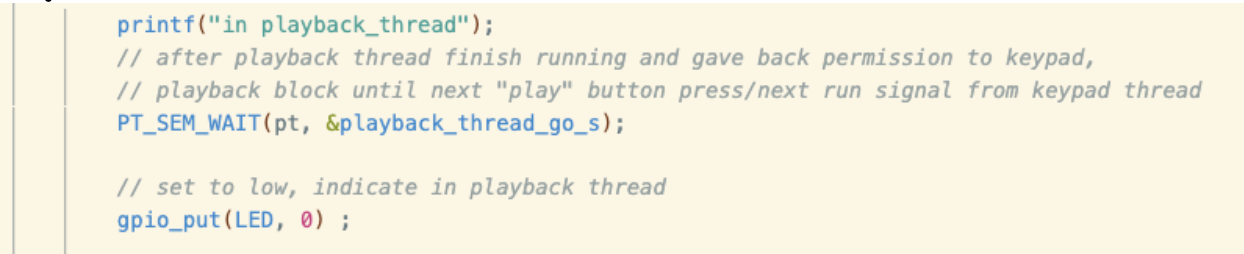
When entering the playback thread, “in playback_thread” prints on serial monitor, and on-board led is off to indicate being inside playback thread. This helps with debugging our program, ensuring alternation of threads.
We did not use a counter to keep track of how many songs are recorded. Instead, we use a for loop to iterate through the recorded_song length 30 array, starting from index 0, producing a song by storing element of current index (“swoop”, “chirp,” or “pause”) to button_number and setting STATE_0 (song production happens in timer ISR), then incrementing to next index and produce that sound, and continue incrementing until reach an empty index, which the for loop breaks. The sleep_us(100) ensures that when sound production is happening (STATE_0 = 0), for loop doesn’t increment and try to produce new song is produced. After breaking from the for loop, with every nonempty index’s element accessed to produce a sound, the array is reset.
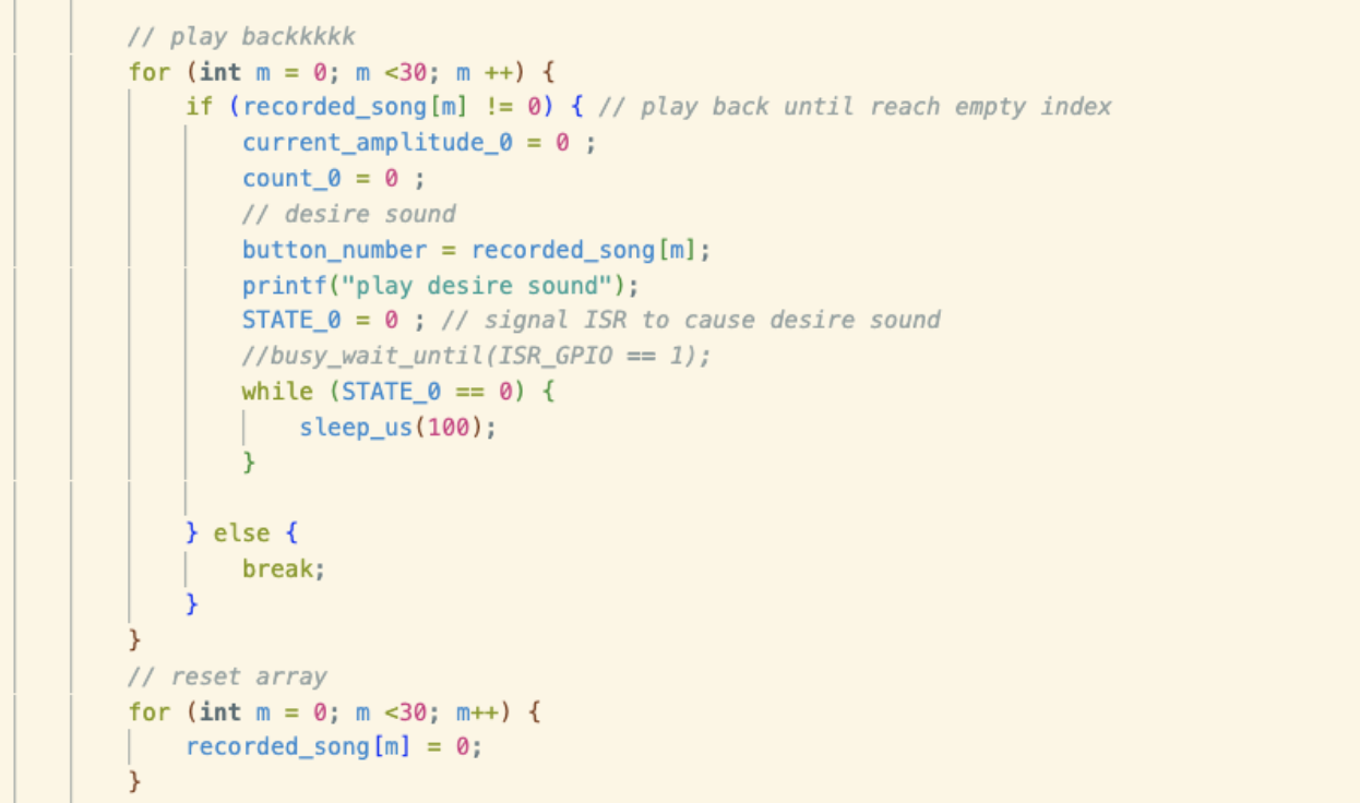
After playback thread finishes running, it signals the keypad thread to run by incrementing the keypad_thread_go_s semaphore. The keypad thread then can scan for new valid keypress.

Hardware:
This project utilizes a Raspberry Pi Pico (RP2040), a digital-to-analog converter (DAC), a button switch (for bootsel) as well as a keypad. Peripheral hardware (keypad and DAC, as well as audio port and bootsel button) are all situated on a breadboard. The keypad, DAC and bootsel button are wired to GPIO pins specified in the provided code, while the audio port is attached to the DAC output and ground.
Result
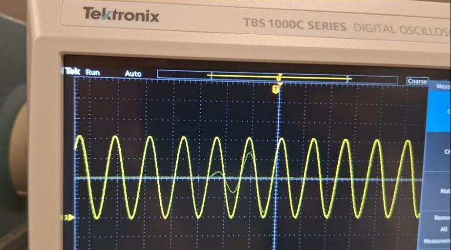
We tested incrementally throughout the three weeks of the lab, meeting all checkoff requirements. The first week we performed testing of the DAC waveform using the oscilloscope (Figure 16), as well as an audial test using the speakers. Additionally, we used a blinking LED to check that the bootsel button worked.
The second week we wired and tested the keypad using provided sample code, then added swoop and chirp functionality to buttons 1 and 2 respectively. We tested the swoop and chirp using oscilloscope and audial verification, as well as using GPIO pin 2 to see the timing of the ISR (Figure 17). All sound primitives spent approximately 130 milliseconds in the ISR.
| Sound Primitive | Time in ISR |
|---|---|
| Swoop | 130 ms |
| Chirp | 130 ms |
| Pause | 130 ms |
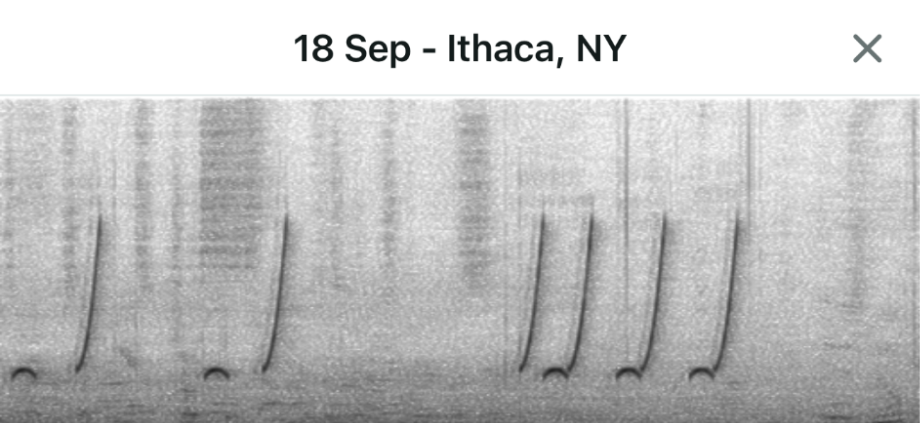
The final week, we completed play and record modes, resulting in a fairly convincing bird song imitation. The spectrogram (Figure 18) displays a marked similarity to the Northern Cardinal call which we hoped to imitate.
One issue we encountered in lab is that there is a deadlock between our keypad thread and payback thread. We commented out the wait operator after the while(1) loop, to resolve the deadlock.
Conclusion
Overall, this project was a successful introduction to the RP2040 and microcontrollers, and we effectively imitated a cardinal’s song. However, if we were to do this lab again, we would try approximating the “swoop” frequency curve as sine functions by utilizing the sine lookup table. We optimized the program by multiplying a value by itself using the multiplication operation instead of the math power function. We can further optimize our program by instead finding its derivatives and using the fundamental theorem of calculus part two. We could also try utilizing the second core on this microcontroller to lift the load per thread. If given more time, we also want to fine-tune our frequency equation more to successfully trick the merlin app.
Work Distribution
Michelle Yang: Wrote most of the code.
Diane Pillsbury: Wrote the initial version of the debouncer code (final version of project, debouncer logic replaced by Michelle's implementation).
Citation
Adams, V. (n.d.). Synthesizing birdsong via direct digital synthesis¶. Birdsong_synthesis. https://vanhunteradams.com/Pico/Birds/Birdsong_synthesis.html